Programming STM32F446RE using SWD connectors
- BalajiV

- Dec 5, 2020
- 1 min read
In this blog, I programmed STM32F446RE using ST-LINK-V2 using SWD connectors

Components:
Hardware Part:
The on-board ST-Link-V2 is connected to the target STM32F446RE via CN2 connector only when the jumpers are ON
By removing both the CN2 jumpers it's not possible to program the STM32F446RE
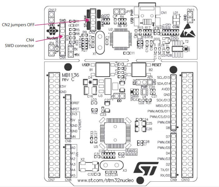
3. After removing the CN2 jumpers, it is possible to program the STM32F446RE using the SWD method, just by connecting the SWDIO PIN and the SWCLK PIN of the ST-Link-V2 from CN4 to the SWDIO and SWCLK of the STM32F446RE

4. Connect the PINs as follows,
ST-LINK-V2 - STM32F446RE
SWCLK - PA14
SWDIO - PA13
Software Part:
After connecting the ST-LINK part of STM32F446RE with the target now, connect to the computer where Keil uVision v5 is installed.
The register level code for blinking the code is here
After creating a project for STM32F446RE and build the code
Select the "Options for Target" option as shown below

5. Select the Debug tab and choose the ST-LINK Debugger from the drop-down box

6. A pop-up box appears as shown below after selecting the "Settings" button near ST-LINK Debugger, select Port as SW and you can see the SW Device section

7. If there is no target then this tab appears as below

8. If the circuit connection is wrong then it appears as below,

9. After successfully loading the code to the board, press the reset button to view the code running on the device.

That's it for now...


Comments